
In this tutorial, we’ll configure an STM32 GPIO pin to be output. Then, we’ll create our first STM32 GPIO Example project (LED Blinking) with a blue pill board. You’ll learn all the steps to configure the STM32 CubeMX & flash the code from STM32CubeIDE to the blue pill board.
We’ll also dive deeper into the STM32 HAL GPIO functions used to control the GPIO output pins in STM32 microcontrollers. Such as the HAL_GPIO_Write() function, HAL_GPIO_TogglePin() function, and more. Without further ado, let’s get right into it!
Objectives of This STM32 LED Blinking Example Project:
Step #1
Open STM32CubeMX, create a new project, and select the STM32F103C8T6 target microcontroller. Note that the STM32 BluePill board has two common target microcontrollers (STM32F103C8T6 & STM32F103C6T6). So you need to select the exact target microcontroller on your hardware board.
This example project should work flawlessly on any STM32 target microcontroller, you just need to select the target MCU that matches your hardware board.
Step #2
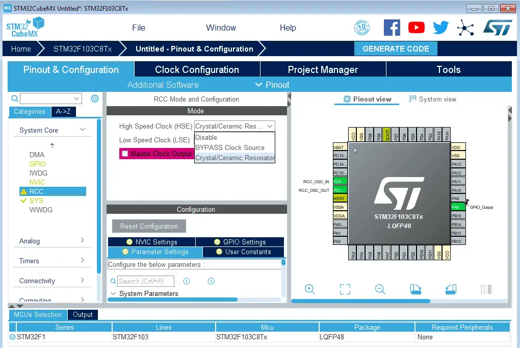
Go to the RCC clock configuration page and enable the HSE external crystal oscillator input.
Click on the PA8 GPIO pin in the “Pinout View” and select it to be in GPIO_Output mode. Note: you can use any other pin you want instead.
Step #3
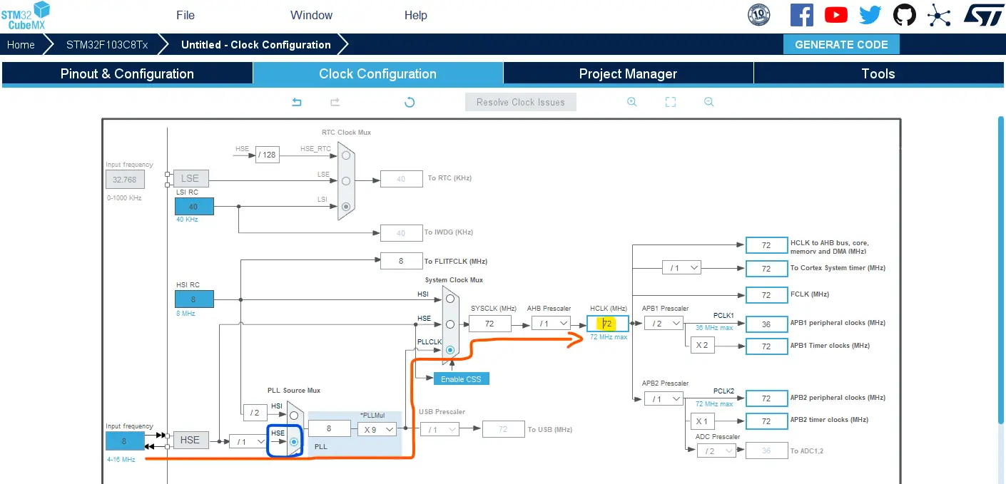
Go to the clock configurations page, and select the HSE as a clock source, PLL output, and type in 72MHz for the desired output system frequency. Hit the “ Enter” key, and let the application solve for the required PLL dividers/multipliers to achieve the desired clock rate.
The reason behind this: using the external onboard oscillator on the BluePill board provides a more accurate and stable clock, and using a 72MHz as a system clock pushes the microcontroller to its limits, so we get the maximum performance out of it. As long as we don’t care about the application’s power consumption.
Step #4
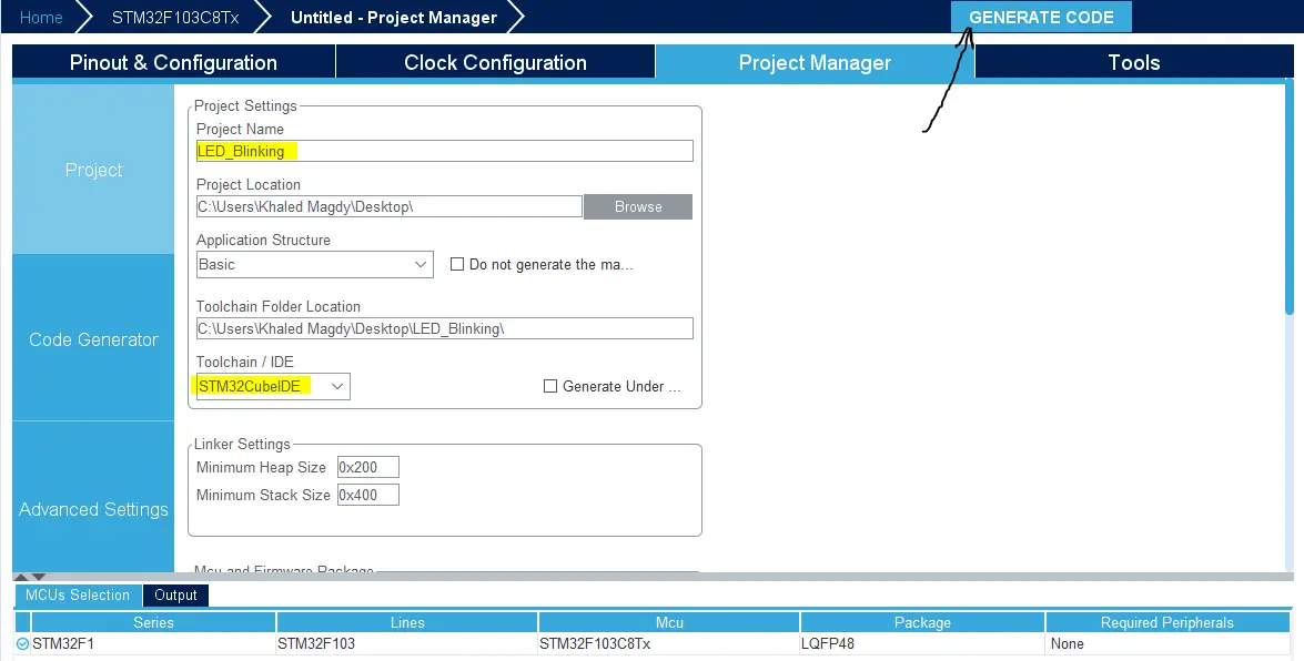
Finally, go to the Project Manager, give your project a name, select the toolchain/IDE to be STM32CubeIDE, and click on the Generate Code button.
The STM32CubeMX tool will generate the initialization code & the project main files and it’ll prompt you to open the project in STM32CubeIDE. Select, open project, and let’s move to the next step.
Then, open the project in the IDE you’re using. And head over to the main.c file. So we can start writing the application code and have a look at the initialization code generated by the STM32 CubeMX tool.
Step #5
Copy the following code into your main.c file replacing the auto-generated code from the beginning of the fill till the main function. You should leave everything else under the main() function in the main.c file as is.
This code example uses the STM32 HAL_GPIO_TogglePin() function.
#include "main.h"

void SystemClock_Config(void);
static void MX_GPIO_Init(void);

int main(void)
{
  HAL_Init();
  SystemClock_Config();
  MX_GPIO_Init();

  while (1)
  {
    HAL_GPIO_TogglePin (GPIOA, GPIO_PIN_8);
    HAL_Delay (100);
  }
}
This code example uses the STM32 HAL_GPIO_TogglePin() function.
#include "main.h"

void SystemClock_Config(void);
static void MX_GPIO_Init(void);

int main(void)
{
  HAL_Init();
  SystemClock_Config();
  MX_GPIO_Init();

  while (1)
  {
    // LED ON
    HAL_GPIO_WritePin(GPIOA, GPIO_PIN_8, GPIO_PIN_SET);
    HAL_Delay(100);
    // LED OFF
    HAL_GPIO_WritePin(GPIOA, GPIO_PIN_8, GPIO_PIN_RESET);
    HAL_Delay(100);
  }
}
You can use any of the previous code examples. Both are doing the exact same functionality (blink an LED every 100ms).
The auto-generated main.c file in the source code directory within our projects was as shown below.
#include "main.h"


void SystemClock_Config(void);
static void MX_GPIO_Init(void);

int main(void)
{

  HAL_Init();

  SystemClock_Config();

  MX_GPIO_Init();

  while(1)
  {

  }

}Both functions SystemClock_Config() and MX_GPIO_Init() are generated by CubeMX to configure the system clock as we’ve done in the GUI before and the GPIO pin which we’ve selected to be an output pin. The implementation of both functions is found in the file after the main function.
We call each of them before the main loop while(1) as well as the HAL_Init function. The HAL_Init must be called at the beginning of your application. Its functionality is clarified in the HAL Documentation as shown below.
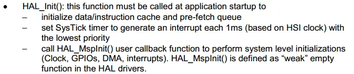
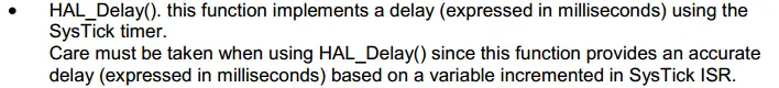
And most importantly it initializes the SysTick timer, whose ticks are used by the HAL_Delay(). The SysTick timer is set to tick @ 1000Hz or every 1mSec. So the HAL_Delay function will give you multiples of milliseconds delay.
Besides the delay function, we also need to know the HAL APIs for controlling the GPIO pins. To do basic stuff like pin read or write or port read/write, and so on.
So we’ll head over again to the HAL documentation and search for the GPIO chapter, where we’ll find this listing for the available APIs. The APIs are hyperlinked in the documentation file, so you can click the name of the function to go directly to its detailed description.
So, let’s take a closer look at the GPIO_WritePin() function, for example.
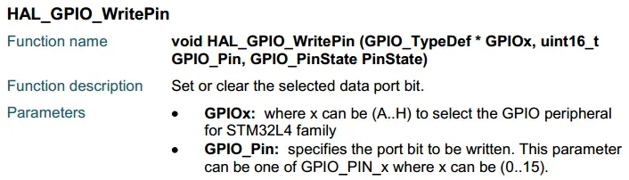
More details on all functions can be found in the STM32 HAL documentation that you can easily find on the STMicroelectronics website.
Step #1
Refer To The Blue Pill Board Schematic & Pinout
Step #2
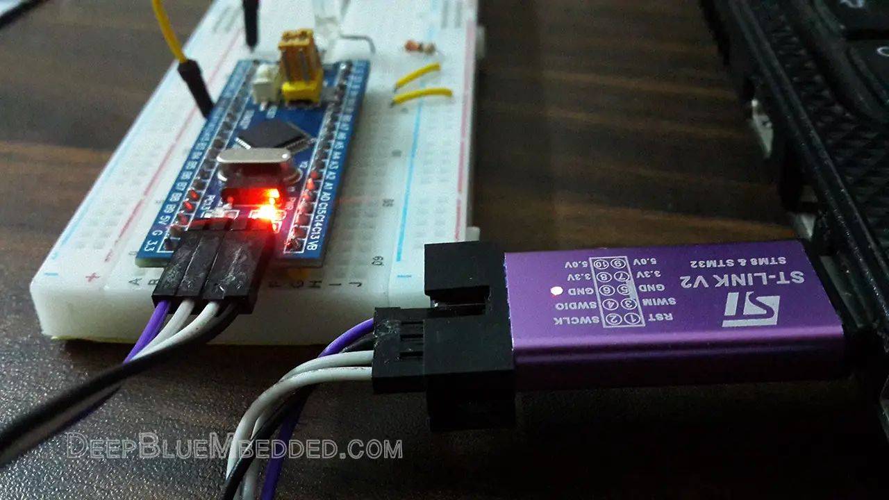
Connect The ST-Link To The USB Port & SWD Pins On Board
Step #3
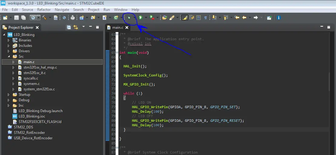
Click The Debug Button To Compile The Code & Flash It To The Board & Start A Debugging Session
Step #4
You Can Stop The Debugging Session Or Keep It Going. But You Need To Restart The MCU Once To Run The New Application At The Booting Process.
Required Parts For STM32 Examples
All the example Code/LABs/Projects in this STM32 Series of Tutorials are done using the Dev boards & Electronic Parts Below:
| QTY. | Component Name | Amazon.com | AliExpress | eBay |
| 1 | STM32-F103 BluePill Board (ARM Cortex-M3 @ 72MHz) | Amazon | AliExpress | eBay |
| 1 | Nucleo-L432KC (ARM Cortex-M4 @ 80MHz) | Amazon | AliExpress | eBay |
| 1 | ST-Link V2 Debugger | Amazon | AliExpress | eBay |
| 2 | BreadBoard | Amazon | AliExpress | eBay |
| 1 | LEDs Kit | Amazon & Amazon | AliExpress | eBay |
| 1 | Resistors Kit | Amazon & Amazon | AliExpress | eBay |
| 1 | Capacitors Kit | Amazon & Amazon | AliExpress & AliExpress | eBay & eBay |
| 1 | Jumper Wires Pack | Amazon & Amazon | AliExpress & AliExpress | eBay & eBay |
| 1 | Push Buttons | Amazon & Amazon | AliExpress | eBay |
| 1 | Potentiometers | Amazon | AliExpress | eBay |
| 1 | Micro USB Cable | Amazon | AliExpress | eBay |
★ Check The Links Below For The Full Course Kit List & LAB Test Equipment Required For Debugging ★
Download Attachments
You can download all attachment files for this Article/Tutorial (project files, schematics, code, etc..) using the link below. Please consider supporting our work through the various support options listed in the link down below. Every small donation helps to keep this website up and running and ultimately supports the whole community.
Copyright ©2025. All Rights Reserved Emblab THE RAVE INNOVATION
