
In this tutorial, we’ll discuss the STM32 ADC Channel Select and how to switch between different ADC channels using HAL functions. You’ll learn how to implement STM32 ADC Multi-Channel
The practical example we’ll implement in this tutorial is an STM32 LED dimmer using multiple potentiometers on multiple analog input pins and multiple PWM outputs to control the brightness of some LEDs. We’ll read the multiple analog input channels (regular group) in single-conversion mode using the ADC Channel select (switch) method. Without further ado, let’s get right into it!
While working with the STM32 ADC with multiple channels being used, you can use the STM32 ADC Scan Mode which will automatically select and convert every single channel in the scan’s regular group of channels. Alternatively, you can disable the scan mode and manually (with software) switch between the ADC channels and convert each one as needed per your application requirements.
Here is how to manually select and switch between 4x different ADC channels and store the conversion result of the 4 channels into an array.
uint16_ti=0,AD_RES[4]; ADC_ChannelConfTypeDef ADC_CH_Cfg={0}; uint32_t ADC_Channels[4]={ADC_CHANNEL_6,ADC_CHANNEL_7,ADC_CHANNEL_8,ADC_CHANNEL_9}; intmain(void) { HAL_Init(); SystemClock_Config(); MX_GPIO_Init(); MX_ADC1_Init(); ADC_CH_Cfg.Rank= ADC_REGULAR_RANK_1; ADC_CH_Cfg.SamplingTime=ADC_SAMPLETIME_1CYCLE_5; while(1) { for(i=0;i<4;i++) { ADC_CH_Cfg.Channel=ADC_Channels[i]; // Select The ADC Channel [i] HAL_ADC_ConfigChannel(&hadc1,&ADC_CH_Cfg); // Configure The Selected ADC Channel HAL_ADC_Start(&hadc1); // Start ADC Conversion @ Selected Channel HAL_ADC_PollForConversion(&hadc1,1); // Poll The ADC Channel With TimeOut = 1mSec AD_RES[i]=HAL_ADC_GetValue(&hadc1); // Read The ADC Conversion Result } } } |
Using the built-in ADC scan mode is more efficient in terms of CPU time and ADC’s throughput overall. However, using the manual channel selection and conversion method (the code example above) that we’ll explain in this tutorial is very flexible and allows achieving any custom applications’ requirements. The STM32 ADC Scan Mode is illustrated in detail in the tutorial linked below (with examples using polling, interrupt, and DMA).

This tutorial will give you more in-depth information about the STM32 ADC Scan Mode and how to read multi-channels of the ADC regular group using (polling, interrupt, and DMA) in single-conversion mode with code examples for each configuration.
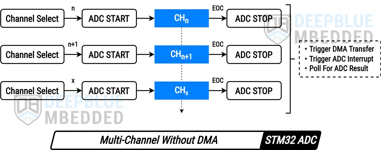
In this tutorial, we’ll explore the STM32 ADC Multi-Channel Without DMA operation in single-conversion (one-shot) mode. In this mode, the ADC will select a desired channel of the regular group and start the conversion process. Upon conversion completion, the application can poll for the ADC result or get an interrupt or DMA notification instead. Then, the ADC can switch to (select) another channel of the regular group and repeat the conversion process.
This manual channel selection & conversion enables us to sample different ADC channels with different periodicities (sampling rates). Here is an illustrative diagram of how this process works.
 Note
NoteFor the multi-channel operation of the STM32 ADC, we can use the auto “scan” mode instead of manually switching between the regular group of channels as show in this tutorial. To learn more about the STM32 ADC Multi-Channel scan mode you can check the following tutorials:
In this example project, we’ll create an STM32 LED Dimmer using ADC & PWM to read multiple analog inputs from 4x potentiometers to control the brightness of 4x PWM outputs going to 4x LEDs. This demo will run the STM32 ADC in multi-channel single-conversion mode without DMA (no scan).
In this LAB, our goal is to build a system that initializes multiple ADC analog input pins (4x channels: 6-9). Also, configure a timer module to operate in PWM mode with 4x outputs on channels 1-4 (4x LED pins).
Then, we can select the ADC regular group channels one by one to start the conversion of each channel sequentially, get the ADC results, map them to the PWM duty cycle registers, and repeat the whole process over and over again.
And now, let’s build this system step-by-step
Step #1
Open STM32CubeMX, create a new project, and select the target microcontroller.
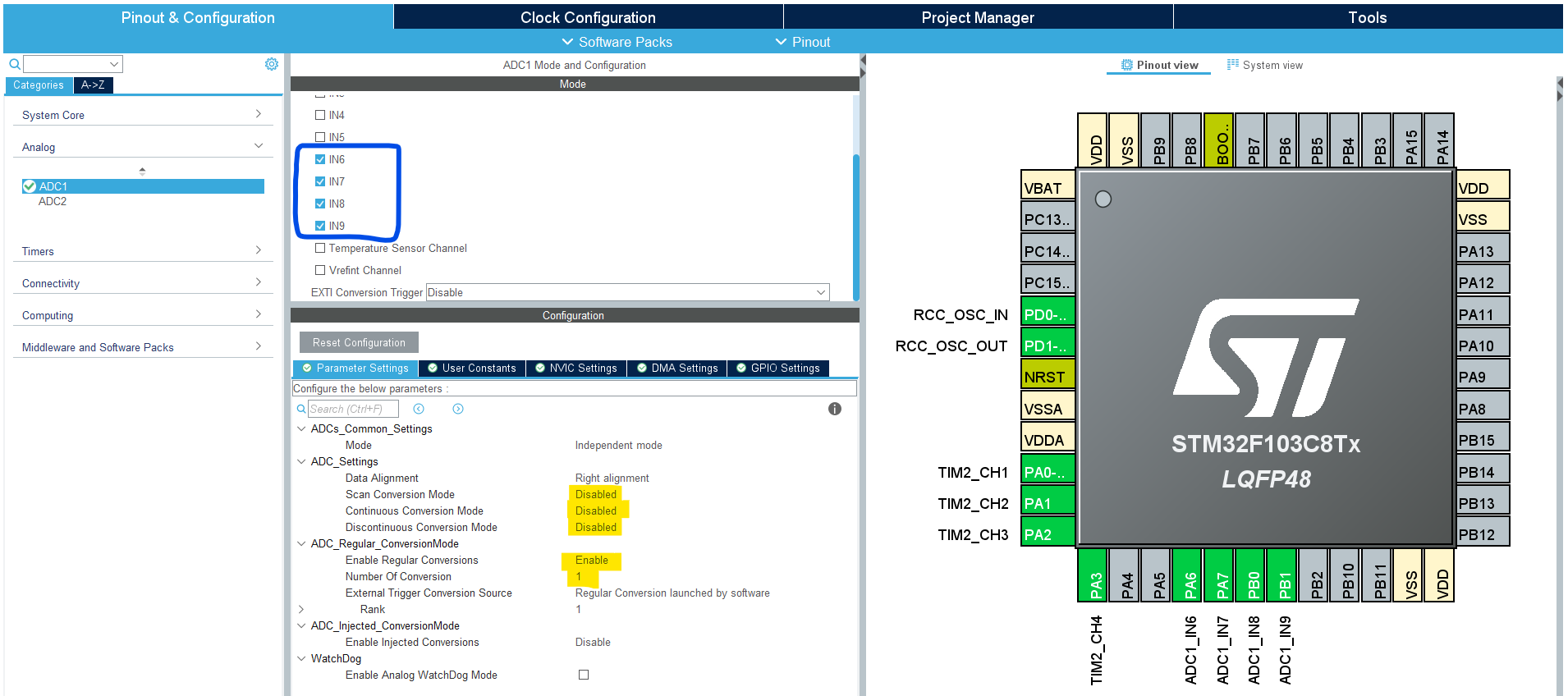
Step #2
Configure The ADC1 Peripheral, Enable the regular Channels: 6-9, and set the number of regular conversions to 1. You’ll find that the analog channel has these default configurations which happens to be ok for us in this example project.
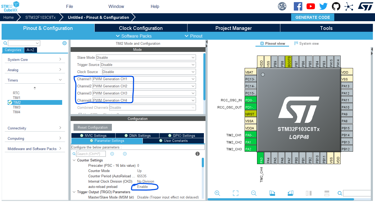
Step #3
Configure Timer2 To Operate In PWM Mode With Output On CH1-4.
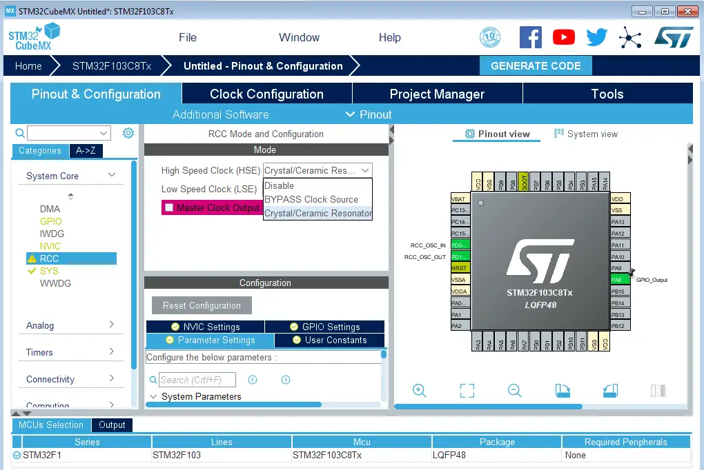
Step #4
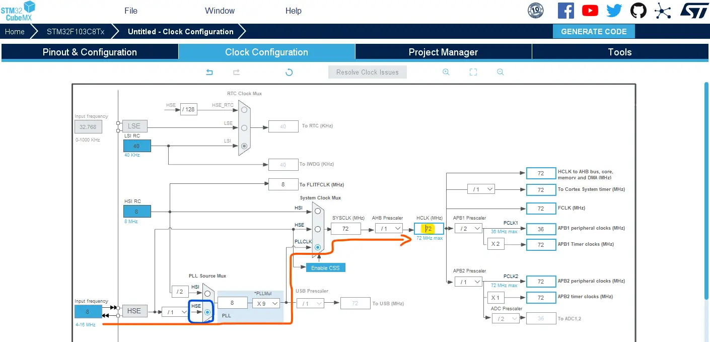
Go to the RCC clock configuration page and enable the HSE external crystal oscillator input.
Step #5
Go to the clock configurations page, and select the HSE as a clock source, PLL output, and type in 72MHz for the desired output system frequency. Hit the “ Enter” key, and let the application solve for the required PLL dividers/multipliers to achieve the desired clock rate.
Step #6
Name & Generate The Project Initialization Code For CubeIDE or The IDE You’re Using.
Here is The Application Code For This LAB (main.c)
/* * LAB Name: STM32 ADC Multi-Channel Without DMA * Author: Khaled Magdy * For More Info Visit: www.DeepBlueMbedded.com */ #include "main.h" ADC_HandleTypeDef hadc1; TIM_HandleTypeDef htim2; uint16_ti=0,AD_RES[4]; ADC_ChannelConfTypeDef ADC_CH_Cfg={0}; uint32_t ADC_Channels[4]={ADC_CHANNEL_6,ADC_CHANNEL_7,ADC_CHANNEL_8,ADC_CHANNEL_9}; voidSystemClock_Config(void); staticvoidMX_GPIO_Init(void); staticvoidMX_ADC1_Init(void); staticvoidMX_TIM2_Init(void); intmain(void) { HAL_Init(); SystemClock_Config(); MX_GPIO_Init(); MX_ADC1_Init(); MX_TIM2_Init(); HAL_TIM_PWM_Start(&htim2,TIM_CHANNEL_1); HAL_TIM_PWM_Start(&htim2,TIM_CHANNEL_2); HAL_TIM_PWM_Start(&htim2,TIM_CHANNEL_3); HAL_TIM_PWM_Start(&htim2,TIM_CHANNEL_4); ADC_CH_Cfg.Rank= ADC_REGULAR_RANK_1; ADC_CH_Cfg.SamplingTime=ADC_SAMPLETIME_1CYCLE_5; while(1) { for(i=0;i<4;i++) { ADC_CH_Cfg.Channel=ADC_Channels[i]; // Select The ADC Channel [i] HAL_ADC_ConfigChannel(&hadc1,&ADC_CH_Cfg);// Configure The Selected ADC Channel HAL_ADC_Start(&hadc1); // Start ADC Conversion @ Selected Channel HAL_ADC_PollForConversion(&hadc1,1); // Poll The ADC Channel With TimeOut = 1mSec AD_RES[i]=HAL_ADC_GetValue(&hadc1); // Read The ADC Conversion Result } TIM2->CCR1=(AD_RES[0]<<4);// Map The ADC_RES1 To PWM1 DutyCycle TIM2->CCR2=(AD_RES[1]<<4);// Map The ADC_RES2 To PWM2 DutyCycle TIM2->CCR3=(AD_RES[2]<<4);// Map The ADC_RES3 To PWM3 DutyCycle TIM2->CCR4=(AD_RES[3]<<4);// Map The ADC_RES4 To PWM4 DutyCycle HAL_Delay(1); } } |
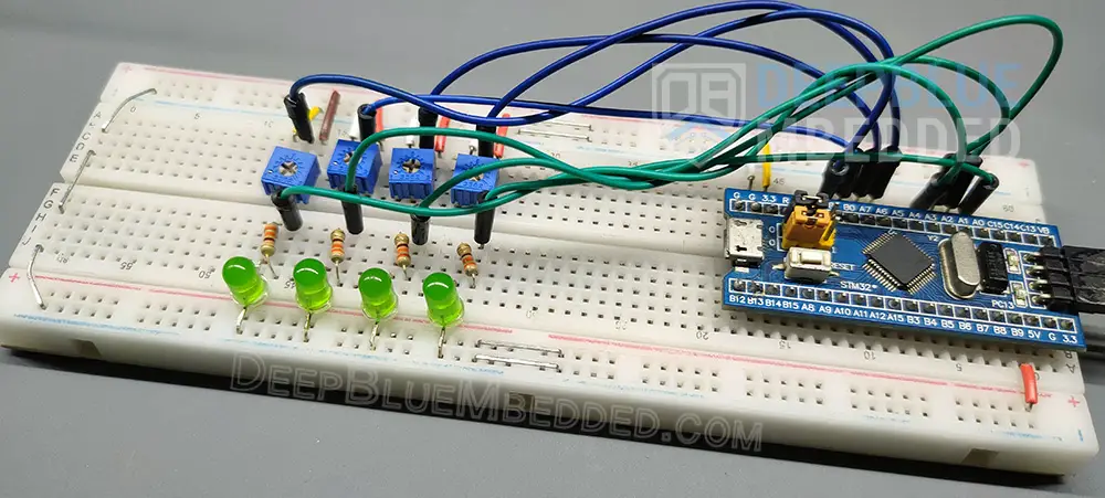
I know that it may look messy, but there isn’t too much about it. These are only 4x LEDs and 4x potentiometers connected to the corresponding GPIO pins on the STM32 blue pill board.
Required Parts For STM32 Examples
All the example Code/LABs/Projects in this STM32 Series of Tutorials are done using the Dev boards & Electronic Parts Below:
| QTY. | Component Name | Amazon.com | AliExpress | eBay |
| 1 | STM32-F103 BluePill Board (ARM Cortex-M3 @ 72MHz) | Amazon | AliExpress | eBay |
| 1 | Nucleo-L432KC (ARM Cortex-M4 @ 80MHz) | Amazon | AliExpress | eBay |
| 1 | ST-Link V2 Debugger | Amazon | AliExpress | eBay |
| 2 | BreadBoard | Amazon | AliExpress | eBay |
| 1 | LEDs Kit | Amazon & Amazon | AliExpress | eBay |
| 1 | Resistors Kit | Amazon & Amazon | AliExpress | eBay |
| 1 | Capacitors Kit | Amazon & Amazon | AliExpress & AliExpress | eBay & eBay |
| 1 | Jumper Wires Pack | Amazon & Amazon | AliExpress & AliExpress | eBay & eBay |
| 1 | Push Buttons | Amazon & Amazon | AliExpress | eBay |
| 1 | Potentiometers | Amazon | AliExpress | eBay |
| 1 | Micro USB Cable | Amazon | AliExpress | eBay |
Copyright ©2025. All Rights Reserved Emblab THE RAVE INNOVATION
