
| Previous Tutorial | Tutorial 7 | Next Tutorial | ||
| STM32 Interrupts Tutorial | NVIC & EXTI | ||||
| STM32 Course Home Page ???? |
In this tutorial, we’ll discuss the ARM cortex interrupts/exceptions, and how priority works. How interrupts are generated and how the CPU switches the context to the ISR and back to the main application. And everything you need in order to configure the NVIC & EXTI correctly and write efficient interrupt service routine handlers (ISR) code. Without further ado, let’s get started!
[toc]
1.1 Exceptions Overview
ARM v7 Core supports multiple great features for handling exceptions and interrupts. Which includes the Nested Vectored Interrupt Controller (NVIC).
Micro-Coded Architecture So that interrupt stacking, entry, and exit are done automatically in hardware. Which offloads this work overhead from the CPU.
The interrupt architecture and priorities are very flexible and highly configurable to support RTOS.
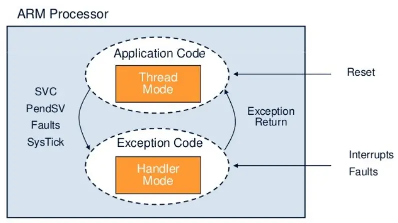
1.2 Processor Mode
The processor mode can change when exceptions occur. And it can be in one of the following modes:
1.3 Micro-Coded Interrupts
The interrupt entry and exit are hardware implemented in order to reduce the latency and speed up the response. The hardware
1.4 Exception Types
Exceptions can be fired by various events including:
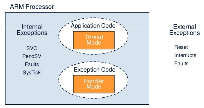
1.5 Internal Exceptions
Exceptions that get fired by an internal source to the system and not by any external hardware or peripherals. And this includes:
1.6 Fault Exceptions
Some of the system exceptions are used to signal and handle specific faults. There are several categories for fault exceptions which include:
1.7 Exception Servicing Model
At the reset state, all interrupts are disabled. The processor begins executing the code instructions with a base execution priority lower than the lowest programmable priority level, so any enabled interrupt can pre-empt the processor.
When an enabled interrupt is asserted, the interrupt is serviced by the corresponding ISR handler. The processor runs the handler at the execution priority level of the interrupt. And when the ISR is done, the original priority level is restored.
When an enabled interrupt is asserted with a lower or equal priority level, the interrupt is pended to run.
The interrupt nesting is always enabled, to disable it just set all the interrupts to the same priority level.
1.8 Exception Behavior
1.9 Reset Behavior
1.10 Exception States
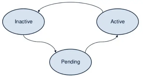
Each exception can be in one of the following states:
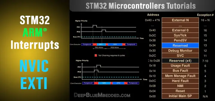
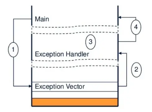
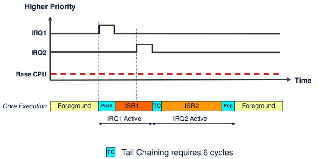
When an interrupt (exception) is fired, the main (foreground) code context is saved (pushed) to the stack and the processor branches to the corresponding interrupt vector to start executing the ISR handler. At the end of the ISR, the context saved in the stack is popped out so the processor can resume the main (foreground) code instructions. However, and if a new exception is already pended, the context push & pop are skipped. And the processor handler the second ISR without any additional overhead. This is called “Tail-Chaining”.
And it requires 6 cycles on Cortex-M3/M4 processors. Which is a huge speedup in the performance and enhanced the interrupt response time greatly (reduces the interrupt latency). Here is an example of what happens if the CPU receives a 2nd interrupt request (IRQ2) while it’s servicing the 1st one (IRQ1).
The ARM core can detect a higher priority exception while in the “exception entry phase” (stacking caller registers & fetching the ISR routine vector to be executed) of another exception. A “late arriving” interrupt is detected during this period. The higher priority ISR can be fetched and executed but the context saving that has been already done can be skipped. This reduces the latency for the higher priority interrupt and, upon completion of the late-arriving exception handler, the processor can then tail-chain into the initial exception that was going to be serviced (the lower priority one).
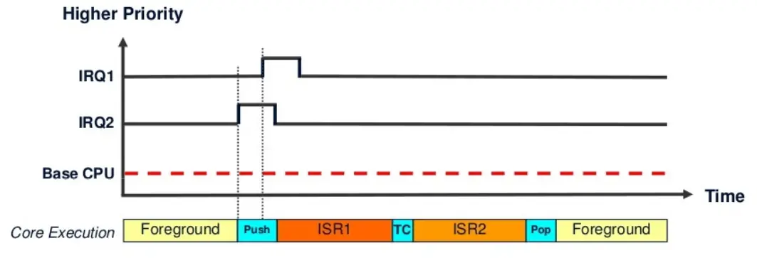
A pending higher-priority exception is handled before an already pending lower-priority exception even after the exception entry sequence has started. The lower-priority exception is handled after the higher-priority exception.
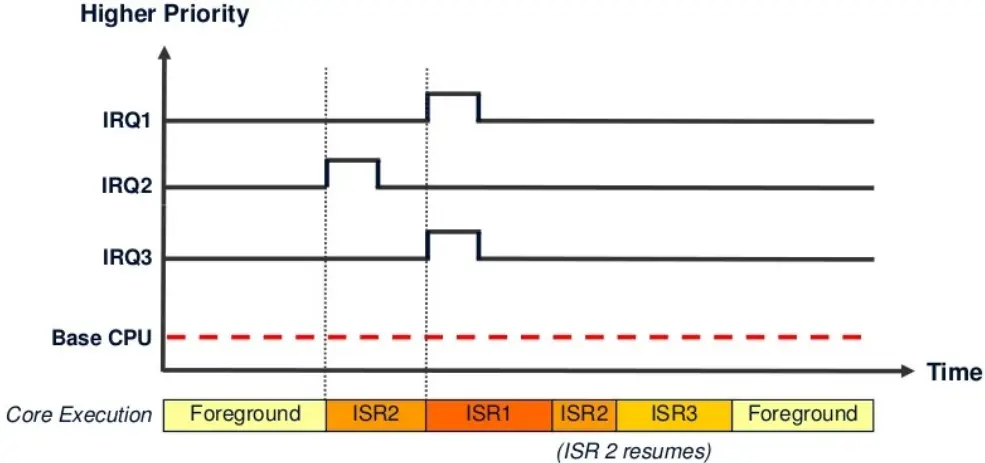
The pre-emption happens when a task is abandoned (gets interrupted) in order to handle an exception. The currently running instruction stream is said to be pre-empted. When multiple exceptions with the same priority levels are pending, the one with the lowest exception number gets serviced first. And once an exception is active and being serviced by the processor, only exceptions with a higher priority level can pre-empt it.
Consider the following example, where 3 exceptions/interrupts are fired with different priority levels. IRQ1 pre-empted IRQ2 and forced IRQ3 to pend until IRQ1 completion. After IRQ1 ISR completion, ISR2 continues where it left off when IRQ1 pre-empted it. And finally, after ISR2 completion, ISR3 starts executions. And the context is restored to the main program (foreground).
The first entry in the table (lowest address) contains the initial MSP. All other addresses contain the vectors (addresses) to the start of exception handlers (ISRs), each address is 4-Byte wide. The table has up to 496 external interrupts which is implementation-dependent on each specific target.
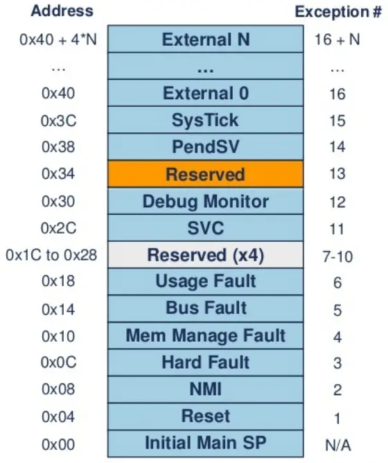
The interrupt vector table may be relocated in the memory easily by changing the value of the vector table offset register. The interrupt/exception vector table is usually located in the startup code file. And it looks something like this down below.
;Vector Table Mapped toAddress0at Reset AREA RESET,DATA,READONLY EXPORT __Vectors EXPORT __Vectors_End EXPORT __Vectors_Size __Vectors DCD __initial_sp ; Top of Stack DCD Reset_Handler ; Reset Handler DCD NMI_Handler ;-14NMI Handler DCD HardFault_Handler ;-13Hard Fault Handler DCD MemManage_Handler ;-12MPU Fault Handler DCD BusFault_Handler ;-11Bus Fault Handler DCD UsageFault_Handler ;-10Usage Fault Handler DCD 0 ; Reserved DCD 0 ; Reserved DCD 0 ; Reserved DCD 0 ; Reserved DCD SVC_Handler ; -5SVCall Handler DCD DebugMon_Handler ; -4Debug Monitor Handler DCD 0 ; Reserved DCD PendSV_Handler ; -2PendSV Handler DCD SysTick_Handler ; -1SysTick Handler ;Interrupts ;ToDo: Add here the vectors forthe device specific external interrupts handler DCD Interrupt0_Handler ; 0Interrupt0 DCD Interrupt1_Handler ; 1Interrupt1 DCD Interrupt2_Handler ; 2Interrupt2 DCD Interrupt3_Handler ; 3Interrupt3 DCD Interrupt4_Handler ; 4Interrupt4 DCD Interrupt5_Handler ; 5Interrupt5 DCD Interrupt6_Handler ; 6Interrupt6 DCD Interrupt7_Handler ; 7Interrupt7 DCD Interrupt8_Handler ; 8Interrupt8 DCD Interrupt9_Handler ; 9Interrupt9 SPACE (214*4) ;Interrupts10..224are left out __Vectors_End __Vectors_Size EQU __Vectors_End-__Vectors |
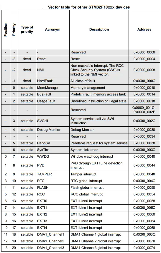
The interrupt vector table for the STM32 ARM microcontrollers we’re using in this course can be found in the corresponding datasheets of these devices. STM32F103C8 And STM32L432KC, it’ll be as shown in the diagram below. It’s only one page of it only for reference, the full table is found in the datasheet itself.
6.1 Interrupt Stacking (Context Saving)
The main program stack is used to store the program state before an interrupt is received. The stack pointer (SP) is automatically decremented on push operation, and it always points to a non-empty value. The stack is 8-Byte aligned and padding may be inserted if it’s required.
When receiving an interrupt signal:
6.2 Interrupt Service Routine (ISR) Handling
The ISR handler should clear the interrupt source if it’s required (Some don’t need to be cleared like the SysTick).
Interrupt nesting won’t affect the way the ISR is written however, attention should be paid to the main stack overflow that may occur.
The ISR C-Code should be written in a clear way, that’s easily readable and easily executed by the processor. Given that certain exceptions/interrupts are to be serviced hundreds or thousands of times per second. So it must run so quickly and no delays are permitted within ISR handlers unless it’s a few microseconds and there is a strong reasoning and justification behind it.
6.3 Return From ISR (Context Restoration)
When an exception (ISR) handler is completely executed and no other interrupts are pending, the CPU restores the context of the main (foreground) application code.
The EXC_RETURN instruction is fetched and gets executed to restore the PC and pop the CPU registers.
If other interrupts are pending, the highest priority will be serviced first, and the context restoration is abandoned to accelerate the interrupt response. This is the tail-chaining feature discussed earlier.
If the context restoration process is interrupted, it gets abandoned. And the new ISR starts execution without the need to save the context because it’s already pushed into the stack.
The return from interrupt (context restoration) on ARM Cortex-M3/M4 requires 10 clock cycles.
The base system execution priority is level is lower than the lowest programmable priority level. So any enabled interrupt when gets fired, it’ll pre-empt the main code execution. Afterward, the corresponding ISR will get executed.
There exist a few ways in software to change the main code execution priority level to make it higher than the default priority of thread mode or the exception that is currently active. This process is called Priority Boosting. And it can be advantageous in many situations, especially in RTOS. When you need to execute some logic without getting interrupted by any source.
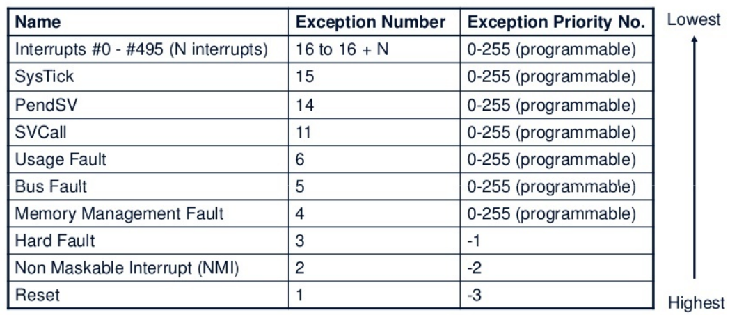
Internal and external exceptions table is found in the datasheet. Some exceptions/interrupts are at a fixed priority level and can’t be changed programmatically. And the lower the priority level number, the higher the priority is. The priority level is stored in a byte-wide register which is cleared (0x00) on reset. If two or more exceptions/interrupts are of the same priority level value, the priority order is therefore determined based on the exception number itself (Lower exception number has a higher priority).
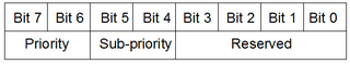
Each exception/interrupt has associated an 8-bit priority level register. But not all bits are used to set priorities. STM32F103C8 MCU has only 16 priority levels which means that 4 MSB bits are used to set priorities. If needed these bits can be split into two groups where you can create sub-priority levels for each preemptive priority. Sub-priority is used only if the group priority is the same.
Sub-priority levels are useful when two or more same priority level interrupts occur. Then, the one with a higher sub-priority will be handled first. And if two exceptions/interrupts are of the same priority levels exactly, the one with lower vector number gets handled first.
EXTI Controller Overview
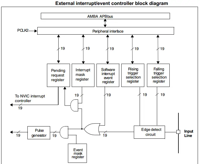
The external interrupt/event controller consists of up to 20 edge detectors in connectivity line devices, or 19 edge detectors in other devices for generating event/interrupt requests. Each input line can be independently configured to select the type (event or interrupt) and the corresponding trigger event (rising or falling or both). Each line can also masked independently. A pending register maintains the status line of the interrupt requests.
EXTI Controller Features
The EXTI controller main features are the following:
EXTI Block Diagram
Functional Description
To generate the interrupt, the interrupt line should be configured and enabled. This is done by programming the two trigger registers with the desired edge detection and by enabling the interrupt request by writing a ‘1’ to the corresponding bit in the interrupt mask register. When the selected edge occurs on the external interrupt line, an interrupt request is generated. The pending bit corresponding to the interrupt line is also set. This request is reset by writing a ‘1’ in the pending register.
Hardware interrupt selection
To configure the 20 lines as interrupt sources, use the following procedure:
EXTI External Interrupts GPIO Mapping
GPIOs are connected to the 16 external interrupt/event lines in the following manner:
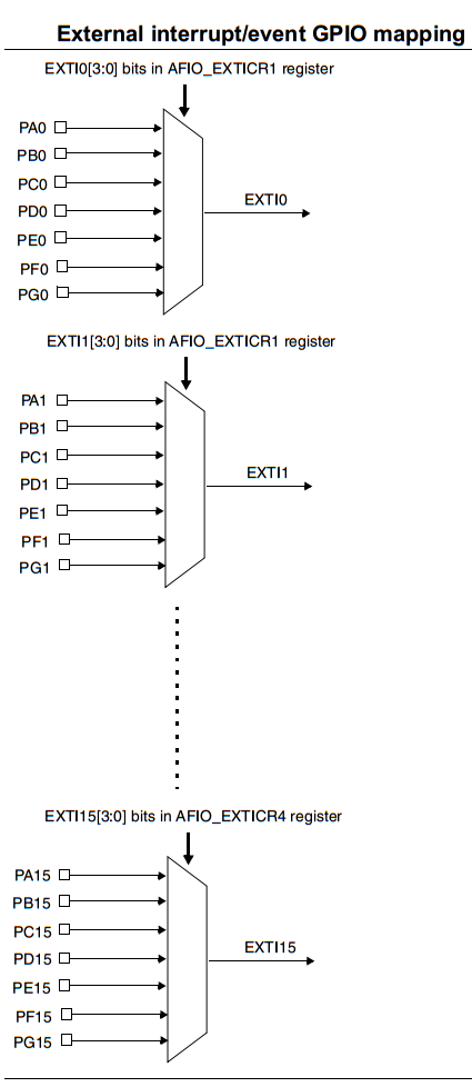
The four other EXTI lines are connected as follows:
We’ll see how to configure the external interrupt pins using the CubeMX software tool in the next tutorial which is going to be a practical LAB for the external interrupts.
Copyright ©2025. All Rights Reserved Emblab THE RAVE INNOVATION
