In this tutorial, we’ll discuss the different possible methods to Read Analog Input With STM32 ADC. You’ll learn how STM32 ADC DMA mode works and how to also use the STM32 ADC Interrupt mode as well as the polling method for the Single-Channel Single-Conversion mode of operation.
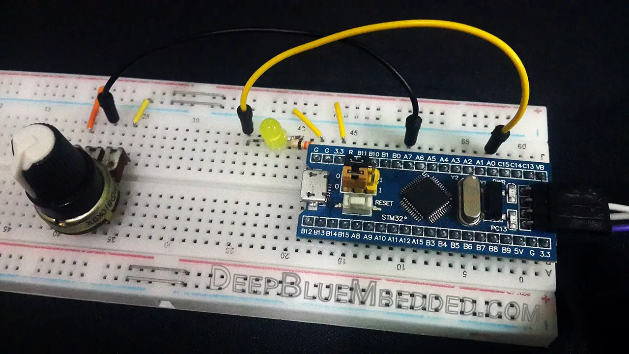
The practical example we’ll implement in this tutorial is an STM32 LED dimmer using a potentiometer to an analog input pin and PWM to control the LED brightness. We’ll read the analog input pin (channel) in single-conversion mode using the DMA, Interrupt, and Polling methods. Without further ado, let’s get right into it!
We can read actually configure the STM32 ADC module to sample a single-channel in single-conversion mode using 3 different methods. Depending on the application type and requirements you can choose the best fit for your situation.
The first of which is the polling method, in this method we’d start an ADC conversion and stop the CPU at this point to wait for the ADC conversion completion. Only after ADC conversion completion, the CPU can resume the main code execution.
The second method is by using interrupts, so we can trigger the ADC in order to start a conversion and the CPU continues executing the main code routine. Upon conversion completion, the ADC fires an interrupt and the CPU is notified so that it can switch the context to the ISR handler and save the ADC conversion results.
Despite being an efficient way, the interrupt method can add so much overhead to the CPU and cause very high CPU loading. Especially when you’re doing so many conversions per second.
And here comes the third method which is using the DMA unit that can directly transfer the ADC result from the peripheral to the memory in the manner that you want and program it to. All that being done without any CPU intervention and upon DMA transfers completion to maybe a 1kb in length buffer, it can notify the CPU to process the data of whatever.
In this example project, we’ll create an STM32 LED Dimmer using ADC & PWM to read an analog input from a potentiometer to control the brightness of a PWM output going to an LED. This demo will run the STM32 ADC in single-channel single-conversion mode using 3 different ADC reading techniques (DMA, Interrupt, and Polling).
The Application will have 3 versions each does the same thing which is read the ADC result and move it to the timer CCR register which decides the PWM duty cycle percentage on the output LED pin.
Example 1, ADC is used in blocking mode (polling)
Example 2, ADC is used in non-blocking mode (interrupt)
Example 3, ADC is used in non-blocking mode (DMA)
In this LAB, our goal is to build a system that initializes the ADC with an analog input pin (channel 7). And also configure a timer module to operate in PWM mode with output on channel 1 pin (LED pin). Therefore, we can start an ADC conversion and map the result to the PWM duty cycle, and repeat the whole process over and over again.
And now, let’s build this system step-by-step
Step #1
Open STM32CubeMX, create a new project, and select the target microcontroller.
Step #2
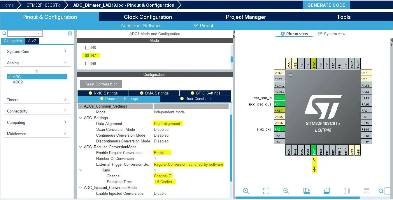
Configure The ADC1 Peripheral, Enable Channel-7 & Set it to be triggered by software. You’ll find that the analog channel has these default configurations which happens to be ok for us in this example project.
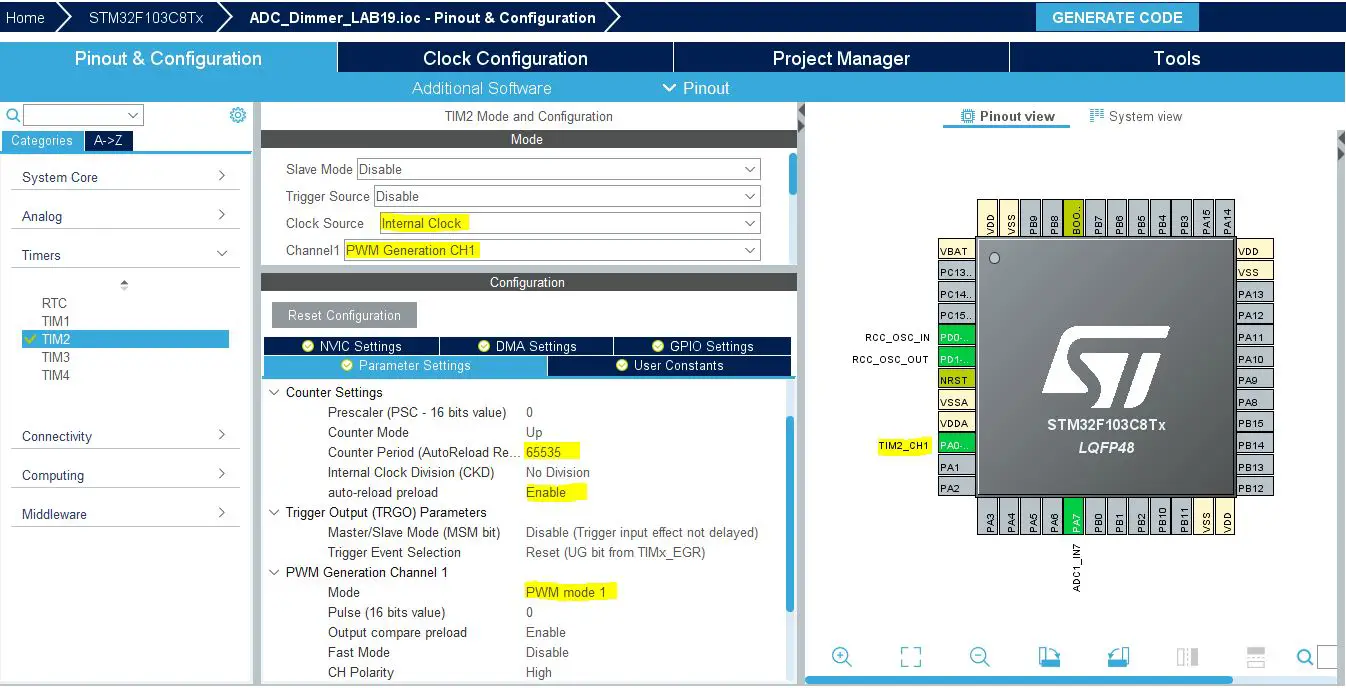
Step #3
Configure Timer2 To Operate In PWM Mode With Output On CH1.
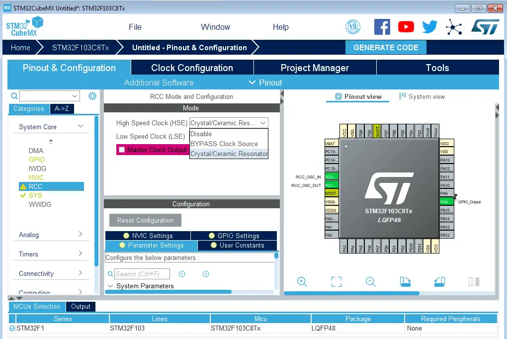
Step #4
Go to the RCC clock configuration page and enable the HSE external crystal oscillator input.
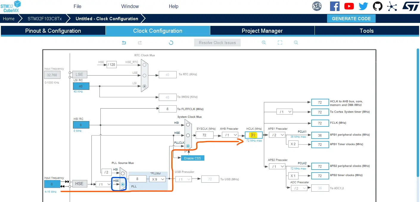
Step #5
Go to the clock configurations page, and select the HSE as a clock source, PLL output, and type in 72MHz for the desired output system frequency. Hit the “ Enter” key, and let the application solve for the required PLL dividers/multipliers to achieve the desired clock rate.
Step #6
Name & Generate The Project Initialization Code For CubeIDE or The IDE You’re Using.
Here is The Application Code For This LAB (main.c)
#include "main.h"

ADC_HandleTypeDef hadc1;
TIM_HandleTypeDef htim2;

void SystemClock_Config(void);
static void MX_GPIO_Init(void);
static void MX_ADC1_Init(void);
static void MX_TIM2_Init(void);

int main(void)
{
    uint16_t AD_RES = 0;

    HAL_Init();
    SystemClock_Config();
    MX_GPIO_Init();
    MX_ADC1_Init();
    MX_TIM2_Init();
    HAL_TIM_PWM_Start(&htim2, TIM_CHANNEL_1);
    // Calibrate The ADC On Power-Up For Better Accuracy
    HAL_ADCEx_Calibration_Start(&hadc1);

    while (1)
    {
       // Start ADC Conversion
    	HAL_ADC_Start(&hadc1);
       // Poll ADC1 Perihperal & TimeOut = 1mSec
    	HAL_ADC_PollForConversion(&hadc1, 1);
       // Read The ADC Conversion Result & Map It To PWM DutyCycle
    	AD_RES = HAL_ADC_GetValue(&hadc1);
    	TIM2->CCR1 = (AD_RES<<4);
    	HAL_Delay(1);
    }
}
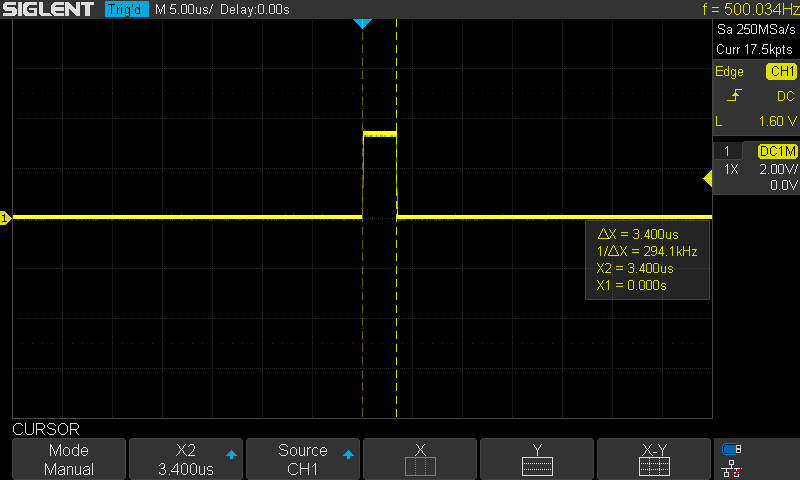
I did configure a GPIO pin to be an output pin and programmed it to toggle HIGH at the beginning of ADC conversion and drive the pin LOW after the polling function immediately. This is to approximately measure the conversion time. Which came out around 3.4μs.
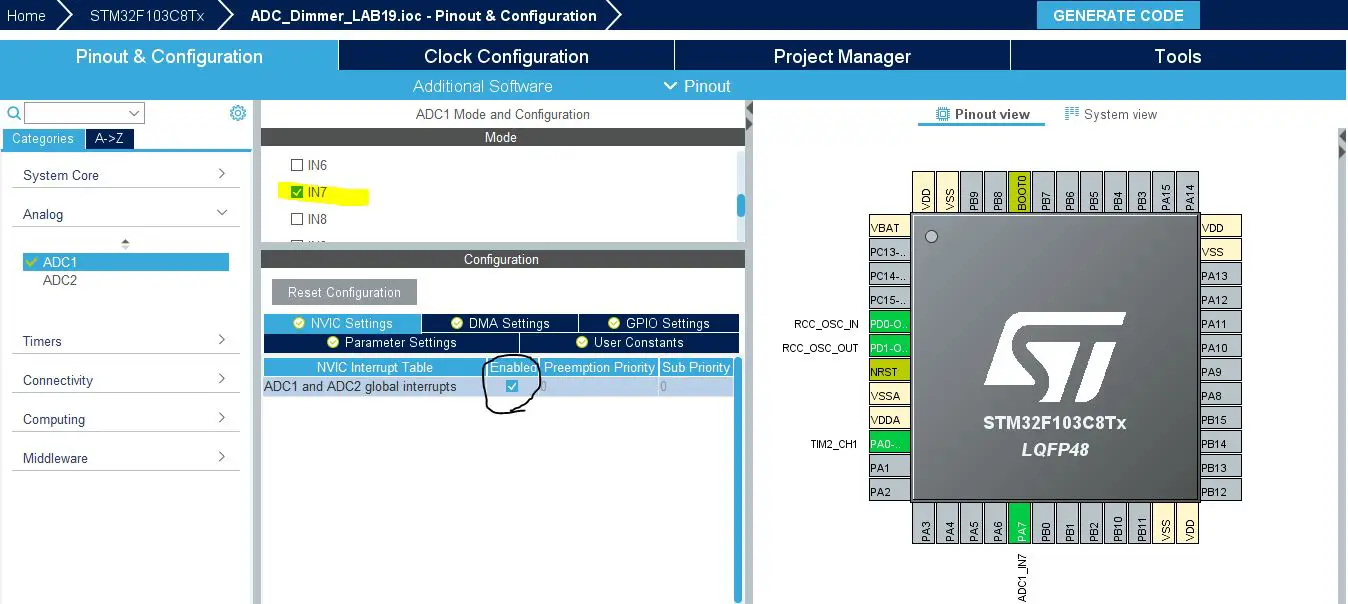
The Exact Same Steps As The Previous Example Except For Step 2. The ADC Configuration Will Be As Follows:
All ADC settings will remain the same but we’ll need to enable the interrupt from the NVIC controller tab.
Generate The Project & Open It In The CubeIDE
Here Is The Application Code Using The Interrupt Method
#include "main.h"

uint16_t AD_RES = 0;

ADC_HandleTypeDef hadc1;
TIM_HandleTypeDef htim2;

void SystemClock_Config(void);
static void MX_GPIO_Init(void);
static void MX_ADC1_Init(void);
static void MX_TIM2_Init(void);

int main(void)
{
    HAL_Init();
    SystemClock_Config();
    MX_GPIO_Init();
    MX_ADC1_Init();
    MX_TIM2_Init();
    HAL_TIM_PWM_Start(&htim2, TIM_CHANNEL_1);
    // Calibrate The ADC On Power-Up For Better Accuracy
    HAL_ADCEx_Calibration_Start(&hadc1);

    while (1)
    {
    	// Start ADC Conversion
    	HAL_ADC_Start_IT(&hadc1);
    	// Update The PWM Duty Cycle With Latest ADC Conversion Result
    	TIM2->CCR1 = (AD_RES<<4);
    	HAL_Delay(1);
    }
}

void HAL_ADC_ConvCpltCallback(ADC_HandleTypeDef* hadc)
{
    // Read & Update The ADC Result
    AD_RES = HAL_ADC_GetValue(&hadc1);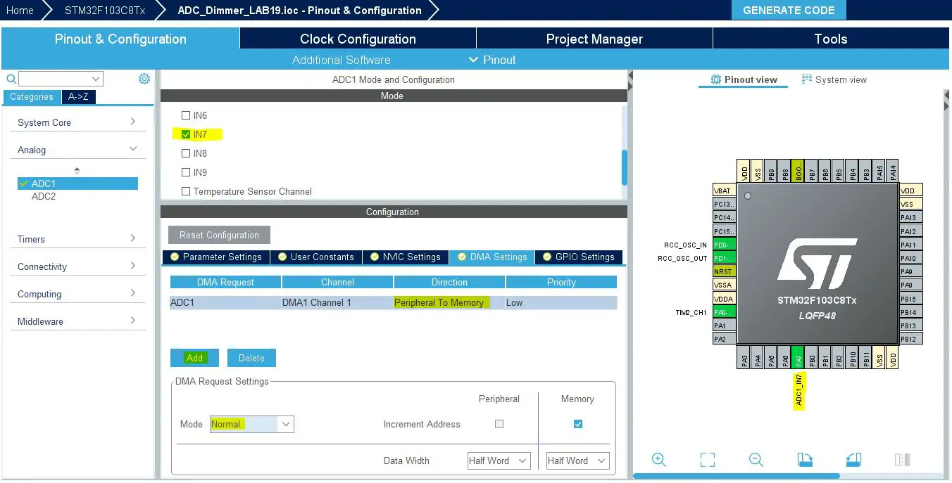
}Also The Exact Same Steps As The First Example Except For Step 2. The ADC Configuration Will Be As Follows:
Everything in ADC configurations will be as default in normal mode. However, this time the STM32 ADC interrupts are not activated and the DMA is configured instead and the DMA interrupt is enabled by default in the NVIC controller tab. The STM32 DMA configurations for the ADC will be as shown down below. Just add a DMA channel and that’s all.
Generate The Project & Open It In The CubeIDE
Here Is The Application Code Using The DMA Method
#include "main.h"

uint16_t AD_RES = 0;

ADC_HandleTypeDef hadc1;
DMA_HandleTypeDef hdma_adc1;

TIM_HandleTypeDef htim2;

void SystemClock_Config(void);
static void MX_GPIO_Init(void);
static void MX_DMA_Init(void);
static void MX_ADC1_Init(void);
static void MX_TIM2_Init(void);

int main(void)
{
    HAL_Init();
    SystemClock_Config();
    MX_GPIO_Init();
    MX_DMA_Init();
    MX_ADC1_Init();
    MX_TIM2_Init();
    HAL_TIM_PWM_Start(&htim2, TIM_CHANNEL_1);
    // Calibrate The ADC On Power-Up For Better Accuracy
    HAL_ADCEx_Calibration_Start(&hadc1);

    while (1)
    {
    	// Start ADC Conversion
    	// Pass (The ADC Instance, Result Buffer Address, Buffer Length)
    	HAL_ADC_Start_DMA(&hadc1, &AD_RES, 1);
    	HAL_Delay(1);
    }
}

void HAL_ADC_ConvCpltCallback(ADC_HandleTypeDef* hadc)
{
    // Conversion Complete & DMA Transfer Complete As Well
    // So The AD_RES Is Now Updated & Let's Move IT To The PWM CCR1
    // Update The PWM Duty Cycle With Latest ADC Conversion Result
    TIM2->CCR1 = (AD_RES<<4);
}
Required Parts For STM32 Examples
All the example Code/LABs/Projects in this STM32 Series of Tutorials are done using the Dev boards & Electronic Parts Below:
| QTY. | Component Name | Amazon.com | AliExpress | eBay |
| 1 | STM32-F103 BluePill Board (ARM Cortex-M3 @ 72MHz) | Amazon | AliExpress | eBay |
| 1 | Nucleo-L432KC (ARM Cortex-M4 @ 80MHz) | Amazon | AliExpress | eBay |
| 1 | ST-Link V2 Debugger | Amazon | AliExpress | eBay |
| 2 | BreadBoard | Amazon | AliExpress | eBay |
| 1 | LEDs Kit | Amazon & Amazon | AliExpress | eBay |
| 1 | Resistors Kit | Amazon & Amazon | AliExpress | eBay |
| 1 | Capacitors Kit | Amazon & Amazon | AliExpress & AliExpress | eBay & eBay |
| 1 | Jumper Wires Pack | Amazon & Amazon | AliExpress & AliExpress | eBay & eBay |
| 1 | Push Buttons | Amazon & Amazon | AliExpress | eBay |
| 1 | Potentiometers | Amazon | AliExpress | eBay |
| 1 | Micro USB Cable | Amazon | AliExpress | eBay |
★ Check The Links Below For The Full Course Kit List & LAB Test Equipment Required For Debugging ★
Download Attachments
You can download all attachment files for this Article/Tutorial (project files, schematics, code, etc..) using the link below. Please consider supporting our work through the various support options listed in the link down below. Every small donation helps to keep this website up and running and ultimately supports the whole community.
In conclusion, we’ve explored the various methods of reading the STM32 ADC single-channel in single-conversion mode using: (DMA, Interrupt, Polling). You can build on top of the examples provided in this tutorial and/or explore the other parts of the STM32 ADC tutorials series for more information about the othe STM32 ADC operating modes and conversion schemes.
Copyright ©2025. All Rights Reserved Emblab THE RAVE INNOVATION