
In this tutorial, we’ll discuss how the STM32 OpAmp (PGA) works, and how to use the STM32 OpAmp with ADC and enable the AWD (analog watchdog) to automatically amplify a current sensor’s reading voltage and trigger a warning signal when it goes out of the AWD voltage window.
The practical example project we’ll implement in this tutorial will be a very good starting point for your STM32 OpAmp-based project. Without further ado, let’s get right into it!
The STM32 OpAmp peripheral is a hardware analog operational amplifier integrated inside the STM32 microcontroller itself. This opamp can be configured to operate in different modes which makes it so flexible and suitable for a wide range of applications.
It can also be referred to as PGA (Programmable Gain Amplifier) because it has an internal switchable array of resistors that allows programmatical change of the opamp’s gain using only software instructions.
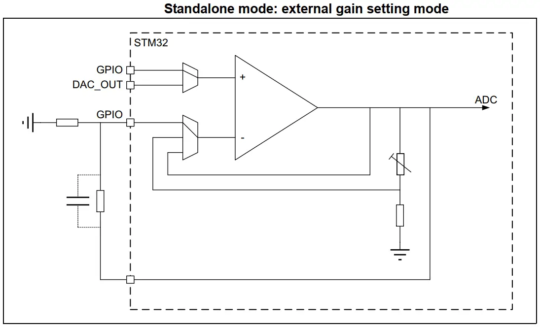
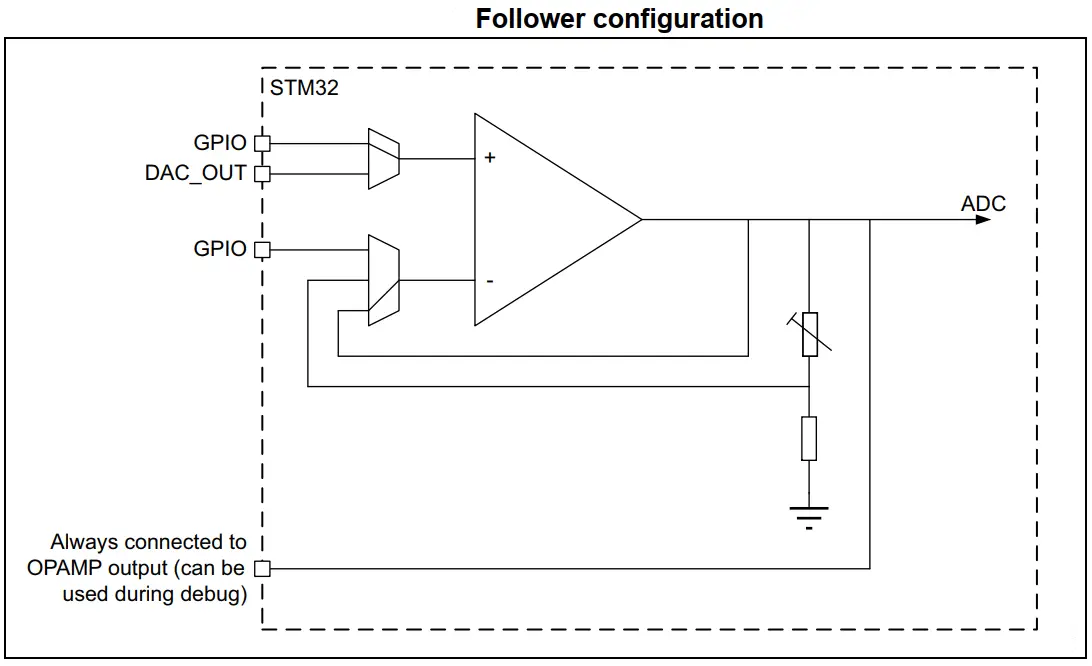
The STM32 OpAmp can be configured to operate in any of the following modes:
| 1. Standalone OpAmp | 2. Voltage Follower OpAmp |
 |  |
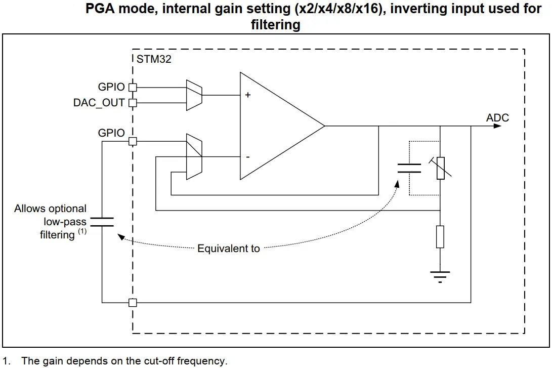
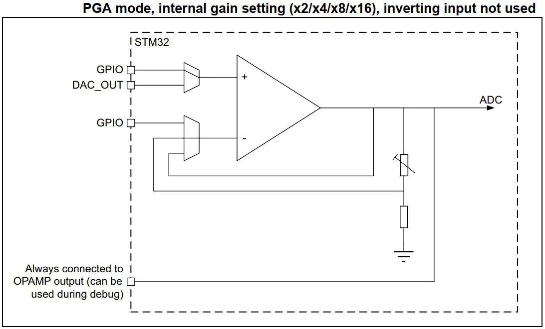
| 3. PGA OpAmp With (Vin-) Pin Exposed | 4. PGA OpAmp With (Vin-) Pin Not Exposed |
 |  |
The STM32 analog OpAmp can be used in so many applications and you can use it in many creative ways especially when configured as a standalone opamp. Here are some common applications for the integrated STM32 OpAmp peripheral:
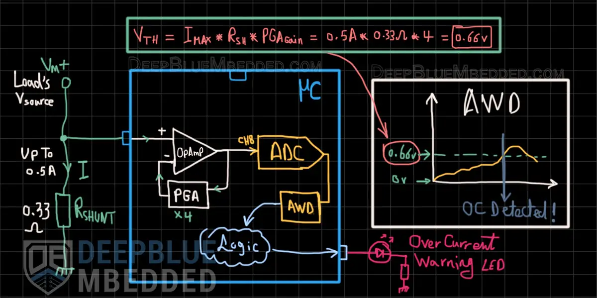
In this example project, we’ll set up the STM32 OpAmp as a PGA (programmable gain amplifier) to amplify the voltage signal of a DC current shunt resistor (0.33Ω) used for measuring the current of whatever load. The voltage of the shunt resistor will be amplified by the internal opamp inside the STM32 microcontroller by a gain of (Gain=4).
The DC current going through the load is desired to have a limit of 0.5A. Therefore, we’ll route the internal opamp’s output to the ADC and configure this ADC’s channel AWD (analog watchdog) to monitor the output voltage of the opamp. When the VOUT of the opamp goes beyond VTH, a warning LED will turn ON indicating an “over current event” and the LED will turn OFF when the current goes back under the 0.5A limit.
Calculating the trip (VTH) voltage is relatively simple, we’ll just use the formula shown in the diagram below.
Example Project Wiring Diagram
Example Project Steps Summary:
This article will give you more in-depth information about the STM32 ADC Analog Watchdog feature, how it works, and how to use it in practical projects with a couple of examples & test codes.
And now, let’s build this system step-by-step
Step #1
Open STM32CubeMX, create a new project, and select the target microcontroller.
Step #2
Set the 1x GPIO B7 as an output pin (for the indicator LED)
Step #3
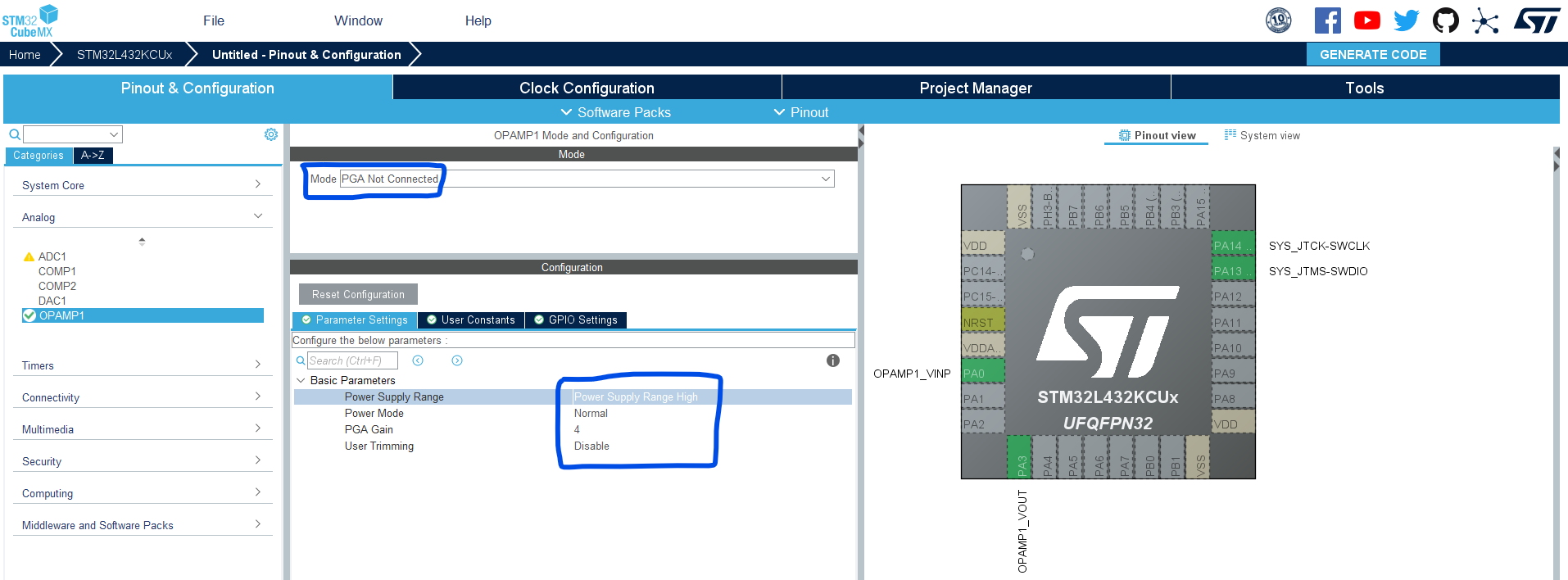
Enable OpAmp1 to operate in the PGA Not Connected mode. Set the gain value to 4 as shown below.
Step #4
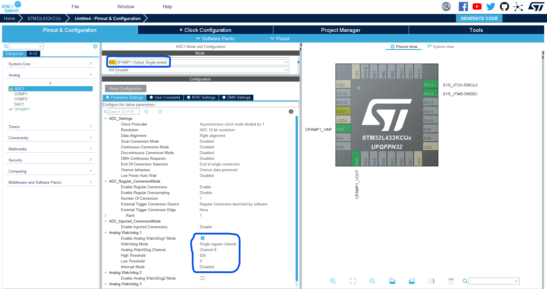
Go to the ADC1, and enable CH8 to operate in OpAmp1 Out Single-Ended mode to route the opamp’s output internally to this ADC’s channel.
Enable The AWD1 (Analog Watchdog1) for CH8, and set the HIGH Threshold to 820 (which corresponds to 0.66v). Note that: (820/4095) * 3.3v = 0.66v
Step #5
Set up system clock, and enable SWD (serial wire debug).
Name & Generate The Project Initialization Code For CubeIDE or The IDE You’re Using.
Here is The Application Code For This LAB (main.c)
/*
 * LAB Name: STM32 OpAmp PGA + ADC + Analog Watchdog Example
 * Author: Khaled Magdy
 * For More Info Visit: www.DeepBlueMbedded.com
*/
#include "main.h"

ADC_HandleTypeDef hadc1;
OPAMP_HandleTypeDef hopamp1;

void SystemClock_Config(void);
static void MX_GPIO_Init(void);
static void MX_ADC1_Init(void);
static void MX_OPAMP1_Init(void);

int main(void)
{
  HAL_Init();
  SystemClock_Config();
  MX_GPIO_Init();
  MX_ADC1_Init();
  MX_OPAMP1_Init();
  HAL_OPAMP_Start(&hopamp1);

  while (1)
  {
	  HAL_ADC_Start(&hadc1);
	  if(HAL_ADC_PollForEvent(&hadc1, ADC_AWD1_EVENT, 1) != HAL_TIMEOUT)
	  {
		  HAL_GPIO_WritePin(GPIOB, GPIO_PIN_7, 1);
	  }
	  else
	  {
		  HAL_GPIO_WritePin(GPIOB, GPIO_PIN_7, 0);
	  }
  }
} Note
NoteYou’ll most probably need to modify the VTH value to suit your application according to: the shunt resistor’s (RSHUNT) value you’re using, the PGA Gain setting, and the desired maximum current (IMAX) at which you want to trigger the warning signal.
Copyright ©2025. All Rights Reserved Emblab THE RAVE INNOVATION
