
In this tutorial, we’ll discuss how the STM32 Internal Analog Comparator works, and how to use the STM32 Comparator with the timer in input capture mode for signal measurement. The STM32 comparator’s output can be externally and/or internally routed to different peripherals which opens the door for a wide range of applications and design ideas as we shall see in this tutorial.
The practical example project we’ll implement in this tutorial will be a very good starting point for your STM32 Comparator-based project. Without further ado, let’s get right into it!
The STM32 comparator peripheral is a hardware analog comparator integrated inside the STM32 microcontroller itself. This analog comparator can be configured to operate in different modes which makes it so flexible and suitable for a wide range of applications.
Let’s now discuss the detailed functionality of the STM32 internal analog comparators, how they work, and what are the possible configurations and operating modes for the analog comparators.
This is the block diagram for the STM32 analog comparators showing its input signal sources and output internal routing options.
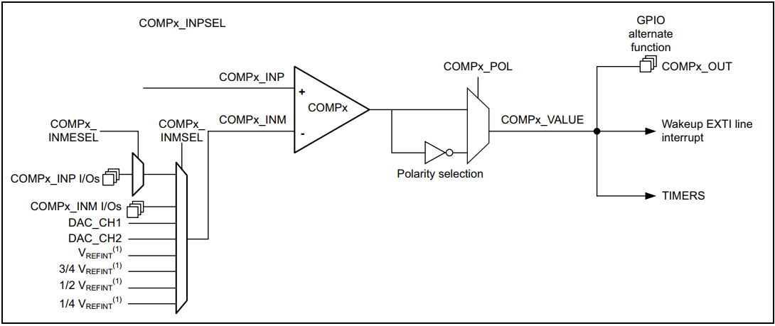
The I/Os used as comparator inputs must be configured in analog mode in the GPIO registers. The comparator output can be connected to the I/Os using the alternate function channel given in the “Alternate function mapping” table in the datasheet. The output can also be internally redirected to a variety of timer inputs for the following purposes:
It is possible to have the comparator output simultaneously redirected internally and externally.
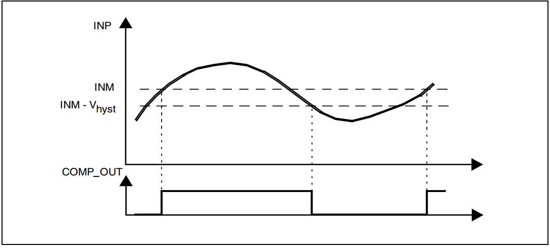
The STM32 analog comparator includes a programmable hysteresis to avoid aggressive fluctuating output transitions in case of noisy input signals.
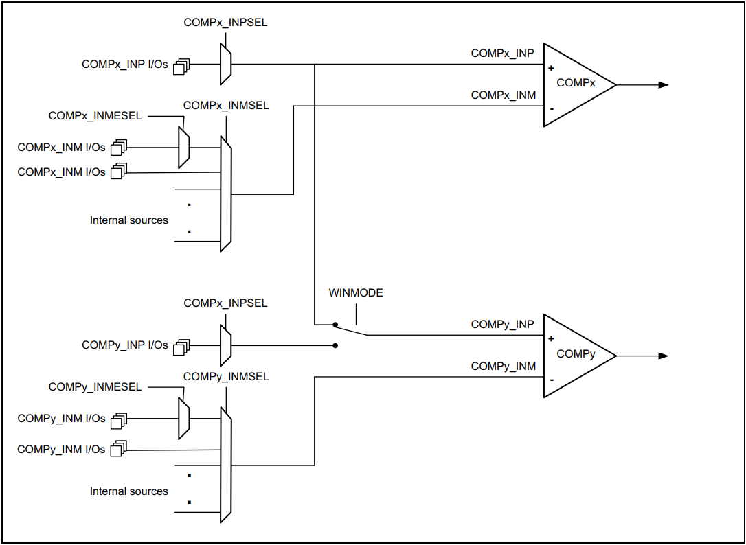
Two embedded comparators can be utilized to create a window comparator. The monitored analog voltage is connected to the non-inverting (Vin+) inputs of comparators connected together and the upper and lower threshold voltages are connected to the inverting (Vin-) inputs of the comparators.
The STM32 analog comparator can be used in so many applications just like a standalone analog comparator but it’s integrated inside the microcontroller itself. Here are some common applications for the integrated STM32 analog comparator peripheral:
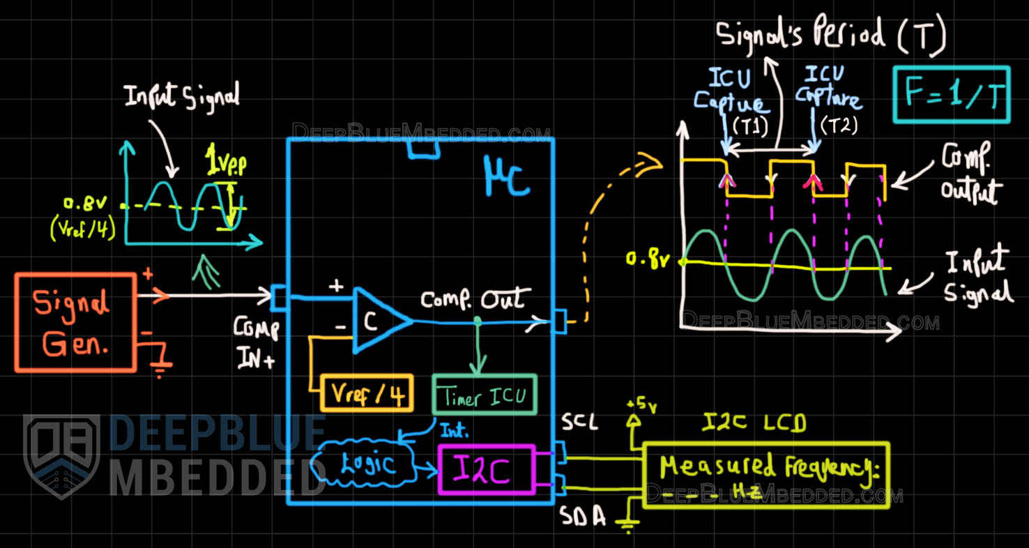
In this example project, we’ll set up the STM32 internal analog comparator to compare the (Vin+), which is coming from a signal generator, against the internal (Vref/4 = 0.825v). Therefore the comparator’s digital output will toggle on the zero-crossing points of the input sinusoidal waveform.
We’ll internally route the comparator’s output (rising edges) as a trigger source for Timer1 which will operate in “input capture” mode. Therefore, an input capture event will be fired on the rising edges of the signal. By taking 2 time stamps for every consecutive ICU event, we’ll easily be able to find out the input signal’s period (T) and, consequently solve for the frequency (F = 1/T).
The resulting frequency measurement will be printed on an I2C LCD. Below is a functional and connection diagram that shows you how this project is working and how things are wired up.
Example Project Diagram
Example Project Steps Summary:
Highly Recommended References Needed For This Project:
This article will give you more in-depth information about the STM32 I2C LCD 16×2 library, how it works, and how to integrate it into your projects.
STM32 Timer Input Capture Unit (ICU) Tutorial
This article will give you more in-depth information about the STM32 Timer modules input capture mode with a frequency counter project example showing you how to set up an ICU for signal frequency measurement.
And now, let’s build this system step-by-step
Step #1
Open STM32CubeMX, create a new project, and select the target microcontroller.
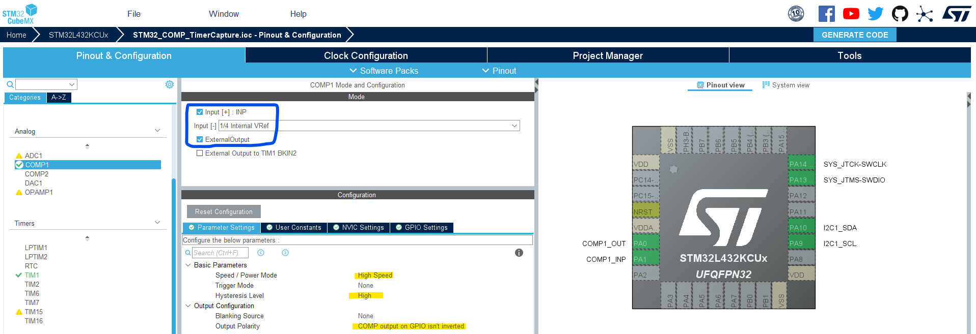
Step #2
Enable COMP1 with IN+, external output pin, and (IN- = Vref/4)
Step #3
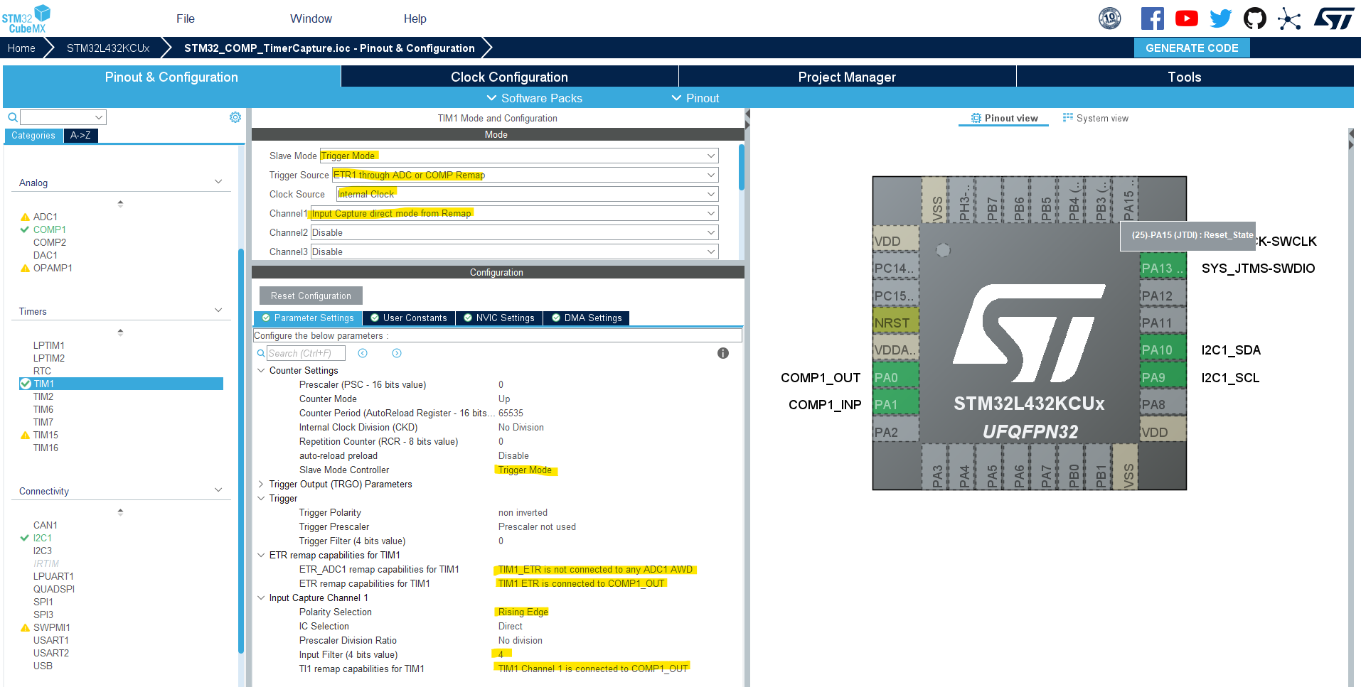
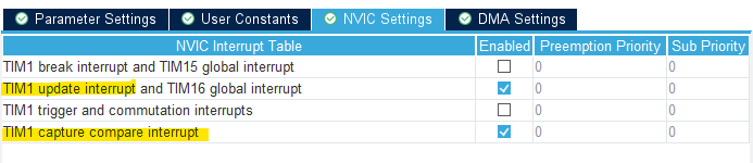
Enable Timer1 in Trigger Mode with ICU on CH1 with the configurations shown below.
Enable Timer1 overflowe (update) interrupt & input chapture1 interrupt as well.
Step #4
Enable the I2C1 peripheral with the default settings as is.
Step #5
Set up system clock, and enable SWD (serial wire debug).
Name & Generate The Project Initialization Code For CubeIDE or The IDE You’re Using.
Step #6
Integrate the I2C_LCD16x2 library as explained in this STM32 I2C_LCD16x2 Tutorial.
Here is The Application Code For This LAB (main.c)
/*
 * LAB Name: STM32 Analog Comparator + Timer Input Capture Example
 * Author: Khaled Magdy
 * For More Info Visit: www.DeepBlueMbedded.com
*/
#include "main.h"
#include <stdio.h>
#include "../../ECUAL/I2C_LCD/I2C_LCD.h"

#define IDLE0
#define DONE1
#define F_CLK  80000000UL
#define MyI2C_LCD I2C_LCD_1

COMP_HandleTypeDef hcomp1;
TIM_HandleTypeDef htim1;
I2C_HandleTypeDef hi2c1;
volatile uint8_t State =IDLE;
volatile uint32_t T1=0;
volatile uint32_t T2=0;
volatile uint32_t Ticks =0;
volatile uint16_t TIM1_OVC=0;
volatile uint32_t Freq =0;
char FreqString[16]={'\0'};

voidSystemClock_Config(void);
staticvoidMX_GPIO_Init(void);
staticvoidMX_COMP1_Init(void);
staticvoidMX_TIM1_Init(void);
staticvoidMX_I2C1_Init(void);

int main(void)
{
HAL_Init();
SystemClock_Config();
MX_GPIO_Init();
MX_COMP1_Init();
MX_TIM1_Init();
MX_I2C1_Init();
HAL_COMP_Start(&hcomp1);
HAL_TIM_Base_Start_IT(&htim1);
HAL_TIM_IC_Start_IT(&htim1,TIM_CHANNEL_1);
I2C_LCD_Init(MyI2C_LCD);

while(1)
{
if(Freq !=0)
{
sprintf(FreqString,"%lu Hz", Freq);
I2C_LCD_Clear(MyI2C_LCD);
I2C_LCD_SetCursor(MyI2C_LCD,0,0);
I2C_LCD_WriteString(MyI2C_LCD,"Measured Frequency:");
I2C_LCD_SetCursor(MyI2C_LCD,0,1);
I2C_LCD_WriteString(MyI2C_LCD, FreqString);
HAL_Delay(300);
}
}
}

voidHAL_TIM_IC_CaptureCallback(TIM_HandleTypeDef* htim)
{
if(State ==IDLE)
{
T1=TIM1->CCR1;
TIM1_OVC=0;
        State =DONE;
}
elseif(State ==DONE)
{
T2=TIM1->CCR1;
        Ticks =(T2+(TIM1_OVC*65536))-T1;
        Freq =(uint32_t)(F_CLK/Ticks);
        State =IDLE;
}
}

voidHAL_TIM_PeriodElapsedCallback(TIM_HandleTypeDef* htim)
{
TIM1_OVC++;
}
The function generator is sending a sine waveform to the STM32 (Comp. IN+ pin). In my test setup, the COMP_OUT digital pin is plotted on the scope’s Yellow Trace, and the input sinusoidal waveform is shown on the Blue Trace.
The measured signal’s frequency is displayed on the I2C_LCD by the STM32 microcontroller.
Copyright ©2025. All Rights Reserved Emblab THE RAVE INNOVATION
